The load capacity of Unistrut members acting as a horizontal beam, between two vertical Unistrut members acting as columns, is governed by:

  • the nature of the load.
  • the particular section to be used.
  • the span of the beam.
  • the beam-load capacity of the section for a given span.
  • the load capacity of the connectors used to support the beams on the columns.
  • the load limitations, if any, resulting from special deflection considerations.

If items a), b) and c) are known, the load capacity is the smallest value of d), e), and f) as read or derived from the listed values in the appropriate tables.

Example 1

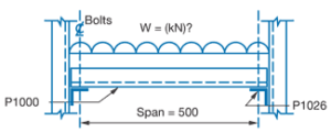
What is the uniformly distributed load capacity of a P1000 section used as a beam to span 500mm if P1026 connectors are used to support the beam?

Step 1

  • Find beam load at maximum permissible stress.
  • From P1000 Beam and Column in this Tab Section, 500mm and Section P1000, W = 7.42kN.

Step 2

  • Find load capacity of connectors.
  • From Safe Bearing Loads in this Tab Section, for P1000 section supported on P1026 connectors;
    Support load = 4.1kN
    Beam load = 2 x support load = 2 x 4.1 = 8.2kN.

Step 3

  • Check deflection limitations.
  • No special deflection considerations apply.

Step 4

  • Select smallest load value from Step 1 to 3.
  • Smallest value is 7.42kN
  • To convert to mass units divide by 0.0098, hence load capacity W = 7.42/0.0098 = 757kg uniformly distributed.


Example 2

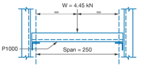
A beam of 250mm span is to carry a central point load of 4.45kN. Check if P1000 section is a satisfactory

Step 1

  • Convert point load to equivalent uniformly distributed load by multiplying by 2 (see note on point loads).
  • Equivalent U.D.L. = 4.45 x 2 = 8.9kN.

Step 2

  • Compare with beam load capacity for P1000 section spanning 250mm. From P1000 Beam and Columns in this Tab Section.
    Tabulated value = 14.83kN.
  • Since this is greater than load to be applied, the P1000 section is satisfactory.

Step 3

  • Determine support loads, which are each half the applied load.
    Support load = 2.23kN.

Step 4

  • Select appropriate connector from Safe Bearing Loads in this Tab Section.
  • Recommended load for P1026 supporting P1000 = 9.5kN.
  • As the P1026 connectors exceed the required support load of 2.23kN, use P1026 connectors at each end.

Step 5

  • Calculate central Deflection of beam from (See P1000 Elements of Section in this Tab Section)
  • From Beam load table for P1000 section with
  • From example data and step 1 above
  • Substituting values in formula

As this is the value for the equivalent uniformly applied load a correction is necessary to account for a central point load. This is done by multiplying the uniform load deflection by 0.8 (see Notes to Tables).
Hence deflection under applied point load:
= 0.10 x 0.8 = 0.08mm.

The load capacity of Unistrut Sections acting as columns depends on:

  • the particular section used.
  • the actual height of the column, measured between centres of connections to horizontal members.
  • the location of the resultant axial load with respect to the centre of gravity, CG, of the section (i.e. the intersection of the XX and YY axes as shown on the section diagrams).
  • the restraint to various kinds of movements of the column offered by the connections to horizontal members at various levels.

If a) and b) are known and if c) and d), for the case being considered, match the conditions in Structural Data Notes then the load capacity of the section can be read directly from the tables under “maximum column load”.

It is emphasised that, for tabulated values to be used directly, the resultant load must be concentric (i.e. act through the C.G.) and connections at each end of a free column height must restrain those ends from both horizontal and torsional movement.

If these conditions do not apply, reference should be made to the appropriate sections of AS/NZS 4600 since it is most likely that a smaller value than the listed one should be used.

Example 3

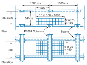
Island-type storage shelving is to be constructed using P1001 main posts (columns) at 1000 x 341mm centres. Shelves are to be at 500mm vertical spacing starting from the floor and connected to the posts so that concentric loading and translational and torsional restraint are provided at each level under full load conditions.

If the shelves are to carry packages of bolts stacked six high per shelf and the packages measure 75 x 75 x 100mm with a mass of 6.5kg each, what is the maximum height (number) of shelving that can be used?

Step 1

  • Determine Concentric load for shelf.
  • Plan area supported by each main column = 1000 x 150 = 150 000mm2
  • This area can be packed with 20 packages 75 x 100mm in plan i.e. 120 packages per shelf.
    Hence mass per shelf = 6.5 x 120kg
    and load per shelf = 6.5 x 120 x 0.0098
    = 7.64kN per column.

Step 2

  • Determine load capacity of P1001 section.
    From P1001 Beams and Columns Table in this Tab
    Section for P1001 with height 500mm.
    Maximum column load = 94.09kN.

Step 3

  • Determine number of shelves.
  • Divide column load capacity by the load per shelf.
    i.e. Number of shelves = 94.09/7.64 = 12.31

    Hence maximum number of shelves = 12
    i.e. max. height of shelving = 12 x 0.5 = 6.0 metres.

Note: If the bottoms of the columns bear onto P1000 bearers, which in turn are fixed to the ground, the load capacity of the column would be determined by the Recommended Bearing Load, (refer to Safe Bearing Loads in this Tab Section) of 30.3 kN. The number of shelves would then be given by: 30.3/7.64 = 3.96

i.e. 3 shelves, totalling 1.5 metres high.