Column Loading Information
Conversion Factors for Beams with Various Static Loading Conditions
Load tables in this catalogue for 41mm channel width series and 32mm channel width series are for single span beams supported at the ends. These can be used in the majority of cases. There are times when it is necessary to know what happens with other loading and support conditions. Some common arrangements are shown in the Table below. Simply multiply the loads from the Beam Load Tables by the load factors given in the Table below. Similarly, multiply the deflections from the Beam Load Tables by the deflection factor given in the table below.
| Factor Table | |||
| Load and Support Condition | Load Factor |
Defledtion Factor |
|
| 1 Simple Beam – Uniform Load | 1.00 | 1.00 | |
| 2 Simple Beam Concentrated Load at Centre | 0.50 | 0.80 | |
| 3 Simple Beam -Two Equal Concentrated Loads at 1/4 Points | 1.00 | 1.10 | |
| 4 Beam Fixed at Both Ends – Uniform Load | 1.50 | 0.30 | |
| 5 Beam Fixed at Both Ends – Concentrated Load at Centre | 1.00 | 0.40 | |
| 6 Cantilever Beam – Uniform Load | 0.25 | 2.40 | |
| 7 Cantilever Beam – Concentrated Load at End | 0.12 | 3.20 | |
| 8 Continuous Beam – Two Equal Spans – Uniform Load on One Span | 1.30 | 0.92 | |
| 9 Continuous Beam – Two Equal Spans – Uniform Load on Both Ends | 1.00 | 0.42 | |
| 10 Continuous Beam – Two Equal Spans – Concentrated Load at Centre of One Span | 0.62 | 0.71 | |
| 11 Continuous Beam – Two Equal Spans – Concentrated Load at Centre of Both Spans | 0.67 | 0.48 | |
| Unistrut® Column Loading | |||
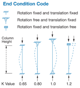
| The strength of axially loaded columns or compression members is, in part, dependent on the end conditions, that is, the degree of end fixity or restraint. A column with both ends fixed will support more load than one with both ends free or pin-ended.
Column loads published for UNISTRUT sections in this catalogue are offered as a guide and assume a partially fixed end condition as usually found in flat ended columns that are laterally tied and braced, i.e. K = 1.0. Assumed K values (effective length factors) for columns with varying end restraints are as follows: |
 |
||